Difference Between Neutral and Ground
The neutral is a special line that runs in the power plants from the so-called wye (star) of the transformer and passes further to the substation. The same neutral line is distributed to houses. Generally, the neutral serves as a balancing line for a three-phase system.
Grounding is exactly what the name says; connection of a device/equipment with a ground in order to pass the current to the ground in order to prevent an electric shock, that is, to protect the people, as well as the device itself.

What is Neutral?
Initial electricians often have a question: “What is a neutral wire in the home power system?” To answer this question, one needs to know that neutral wires are needed to avoid “dominant use of one phase”. Experts strive to achieve a unique load of consumer power.
In order to clearly understand the phenomenon, we will take as an example a building, in which the same number of apartments is connected to one of the three phases. However, unequal consumption in this case still remains. After all, people in every apartment use different electrical appliances at different times of day and night. The current reaches the consumers from a voltage transformer, which is able to convert the network voltage into the secondary winding of the transformer in the “wye” scheme. This scheme connects the three wires at one point called a “zero or neutral” point. The other end of the high voltage wire is output to terminals under the name A, B and C. The connected ends together at the neutral point are connected to the ground loop in the substation. There is, also, a separation of the high voltage wire of zero resistance at:
- protective PE conductor (yellow-green color);
- working neutral (blue).
The described scheme is applied in new buildings. It’s called the TN-S system. In the switchboard of the building, electricians are supplied with 3 phases, PE conductor, and with neutral wire. In most of the old apartment houses there are no PE conductors. The power supply system consists of 4 wires, called TN-C. This scheme is outdated and is considered unsafe. The earth wire in this case is performed individually at the building. Phases and neutrals from the voltage transformers are carried out to the living space by means of underground or overhead high-voltage wires, which further are connected to the front panel of the house. Thus a three-phase system with a voltage of 380/220 volts is formed. From the front panel, electricians set up wires at the entrances and apartments. Electricity is supplied to consumers using wires connected to one of the three phases with a voltage of 220 volts. Also, a protective PE wire is used (only when using the new TN-S system). When neutral conductors are carried to every consumer of electricity, the unbalanced load on the network virtually disappears.

What is Ground?
For additional protection of the house, a protective wire or PE is required. In case of a short circuit, it removes current from the wiring site, which protects people from electric shock and property from a fire. In such a network, the load is evenly distributed, since on each floor of the multi-residential house (building) wiring takes place in stages. The electrical system brought into the apartments is connected in a “wye” scheme, which copies all the vector characteristics of the transformer substation. Such a system is reliable and optimal, but it also has its own faults as periodic problems occur. Electricity shortages are most often associated with poor wire quality, as well as a poor quality of their connection. The main task of the protective wire is to protect the phase conductors from a direct lightning strike. In addition, the protective wire ensures a sufficiently low zero impedance of the line, which contributes to the reliable operation of the protection system in case of short circuit conditions. It also achieves a galvanic connection between the grounding conductors and thus improves the grounding systems of all lines. The protective conductor for the purpose of protecting the conductors from a direct lightning strike can be made of steel ropes, but for other purposes it would be desirable to be made of a better conductive material such as aluminum clad steel.
Difference Between Neutral and Ground
-
Purpose of Neutral and Ground
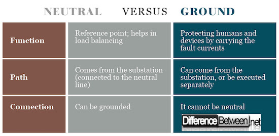
The neutral serves as a reference point in the electrical installation. The neutral conductor, thus is a normally a current-carrying conductor. It has a role in load balancing. The ground is normally not a current-carrying conductor. The ground provides an electrical path to the ground, in case of fault occurrence in the circuit, or in case of a lightning strike.
-
Execution for Neutral and Ground
The neutral conductor is connected to a transformer in a wye connection system. From this point, the line is carried to the end – users. The neutral can be grounded (connected with the ground conductor) in a so-called TN-C system – common conductor acting as a protective and neutral wire. In case there are separate wires the system is TN-S (and is recommended). The grounding can be also carried from the transformer station, or can be executed a separate system for the building.
Neutral vs. Ground

Summary of Neutral and Ground
- The neutral wire serves as a reference point, used for load balancing in the system. It is connected to the “star” point of the transformer. Can be grounded.
- The ground wire is a protective conductor, protecting humans and devices in case of fault occurrence or lightning strikes.
- Difference Between Thermodynamics and Kinetics - June 24, 2018
- Difference Between Welding and Soldering - June 24, 2018
- Difference Between Additive Colors and Subtractive Colors - June 20, 2018
Search DifferenceBetween.net :
Leave a Response
References :
[0]Stokes, G. “Handbook of Electrical Installation Practice”, 4th Edition, NJ: Blackwell Science Ltd, 2003. Print
[1]Linsley, T. “Basic Electrical Installation Work”, 5th Edition, Oxford: Elsevier Ltd., 2008. Print
[2]Donnelly, E. L. “Electrical Installation - Theory and Practice”, 3rd Edition, Oxford: Oxford University Press, 2014. Print
[3]Image credit: https://upload.wikimedia.org/wikipedia/commons/thumb/d/d1/California-3-way.svg/800px-California-3-way.svg.png
[4]Image credit: https://commons.wikimedia.org/wiki/File:067-DaisyChain-Ground.jpg#/media/File:067-DaisyChain-Ground.jpg
