Difference Between Synchronous and Asynchronous Counter
In digital electronics, counter is a sequential logic circuit consisting of a series of flip-flops. It counts the number of occurrences of input in terms of negative or positive edge transitions. They are used in applications such as event synchronization and frequency measurement, estimation of angular position and the duration of an event. Counters are quite similar to registers as both comprise a cascaded arrangement of more than one flip-flop with or without combinational logic devices. Counters are mainly used for counting applications. The count represents the number of clock pulses arrived. Based on the way the flip-flops are triggered, counters can be classified into two major categories: synchronous and asynchronous counter. In a synchronous counter, all the flip-flops are triggered by the same clock signal whereas in an asynchronous counter, flip-flops are triggered with different clock signals. Unlike an asynchronous counter, the state of the output bits changes simultaneously in a synchronous counter, without any ripple. Let’s take a look at the differences between the two.

What is Synchronous Counter?
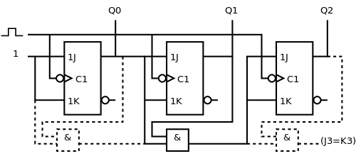
In a synchronous counter, also known as a parallel counter, all the flip-flops in the counter change state at the same time in sync with the input clock signal. When counter is clocked such that each flip-flop in the counter is triggered by the same clock signal at the same time, the counter is called as synchronous counter. It differs from asynchronous counters in that the count pulse input is connected to the clock inputs of all the flip-flops. Because all the flip-flops are clocked at the same time, a synchronous counter with the same number and type of flip-flops can operate at much higher clock frequencies than asynchronous counters. As the clock signal is simultaneously applied to the clock inputs of all the flip-flops, there is no time lag between the different outputs.

What is Asynchronous Counter?
An asynchronous counter is often called a ripple counter. In a ripple counter, the output of one flip-flop drives the other. It is a cascaded arrangement of flip-flops where output of one flip-flop drives the clock output of the following flip-flop. A ripple counter consists of a series of complimenting flip-flops where the output of each flip-flop is connected to the clock input of the next higher-order flip-flop. The clock signal is directly applied to the first flip-flop only and it is subsequently transmitted, with a time delay from one flip-flop to another. For instance, the output of the first flip-flop is the clock input of the second flip-flop, and the output of the second flip-flop is the clock input of the third flip-flop, and so on. Because of the propagation delay, ripple counters are usually slower than their synchronous counterparts in operation.
Difference between Synchronous and Asynchronous Counter
Clock Input
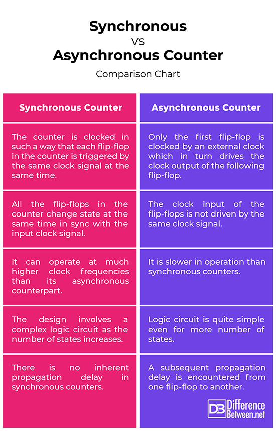
– In a synchronous counter, the same source is used by the clock input across all the flip-flops, creating the same signal at the same time, meaning the counter is clocked in such a way that each flip-flop in the counter is triggered by the same clock signal at the same time. On the contrary, in an asynchronous counter (also called ripple counter) only the first flip-flop is clocked by an external clock which in turn drives the clock output of the following flip-flop. In a ripple counter, the output of one flip-flop drives the other.
Operation
– All the flip-flops are clocked at the same time, thus a synchronous counter with the same number and type of flip-flops can operate at much higher clock frequencies than its asynchronous counterpart. It differs from asynchronous counters in that the count pulse input is connected to the clock inputs of all the flip-flops. In an asynchronous counter, no common clock is used meaning the clock input of the flip-flops is not driven by the same clock signal. On the contrary, in a synchronous counter, every flip-flop is triggered by the common clock pulse.
Time Delay
– Because the clock signal in a synchronous counter is applied to the clock inputs of all the flip-flops at the same time, there is no time lag between the different outputs. So, there is no inherent propagation delay in synchronous counters. In an asynchronous counter, the clock signal is directly applied to the first flip-flop only and it is subsequently transmitted, which results in a subsequent time delay from one flip-flop to another, which eventually accounts for its low speed operation compared to synchronous counter.
Synchronous vs. Asynchronous Counter: Comparison Chart

Summary
In a synchronous counter, all the flip-flops are triggered by the same clock signal and the outputs of the counter change state at the same time, so there is no inherent propagation delay between the different outputs. In an asynchronous counter, in contrast with synchronous counters, the clock input of the flip-flops is not triggered by the same clock signal; in fact, the output of one flip-flop drives another. This results in a subsequent time lag between the outputs from one flip-flop to another. On the contrary, there is no inherent time lag between the outputs in a synchronous counter.
- Difference Between Caucus and Primary - June 18, 2024
- Difference Between PPO and POS - May 30, 2024
- Difference Between RFID and NFC - May 28, 2024
Search DifferenceBetween.net :
Leave a Response
References :
[0]Image credit: https://upload.wikimedia.org/wikipedia/commons/thumb/f/ff/Asynchronous-counter2.svg/500px-Asynchronous-counter2.svg.png
[1]Image credit: https://upload.wikimedia.org/wikipedia/commons/thumb/a/ad/3_bit_up_synchronous_counter.svg/500px-3_bit_up_synchronous_counter.svg.png
[2]Langholz, Gideon, et al. Foundations of Digital Logic Design. Singapore: World Scientific, 1998. Print
[3]Ndjountche, Tertulien. Digital Electronics 2: Sequential and Arithmetic Logic Circuits, Volume 2. Hoboken, New Jersey: John Wiley & Sons, 2016. Print
[4]Kal, Santiram. BASIC ELECTRONICS: DEVICES, CIRCUITS AND IT FUNDAMENTALS. New Delhi, India: PHI Learning, 2009. Print
