Difference Between Capacitor and Resistor
Capacitor Vs. Resistor
There are three basic components found in electronic circuits, capacitor, resistor, and inductor. These individual components play an important role in how an electronic circuit behaves, with each connected by conductive wires through which electric current can flow. These components are generally classified into two classes as active and passive components. Components capable of controlling current by means of another electrical signal are called active components, whereas passive components are the ones that respond to the flow of current and either dissipate or store energy. Active components require some sort of external power source to be triggered. Resistors and capacitors are passive components, whereas transistors are classified as active components of an electronic circuit. This article helps you better understand the two basic electronic components in detail and the difference between the two.

What is Resistor?
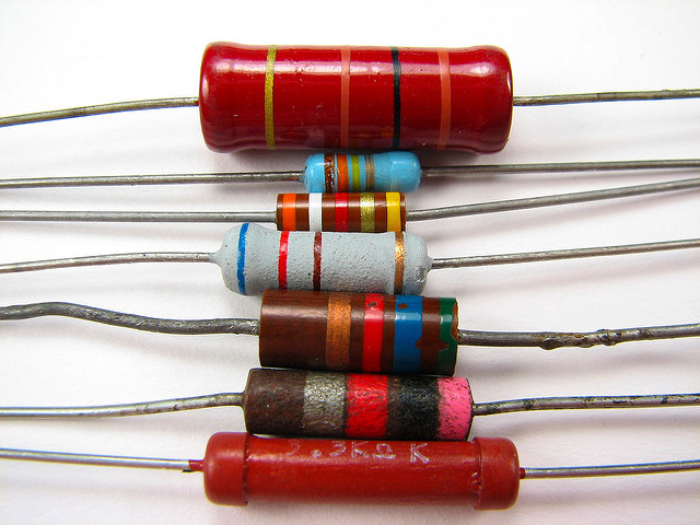
Resistors are fundamental components in electrical and electronic circuits used to control voltage and current values in circuits. They are basically energy-consuming elements that limit the flow of current to have the right amount of current and voltage that you want precisely in your circuits. A resistor is used where more current is required to be impeded so that the desired amount of current is achieved without any resistance. They are passive two-terminal components that implement resistance to reduce the flow of current to a safe value. They convert electrical energy into heat, which is then dissipated into the air. Resistors are generally classified into two types: fixed and variable. Resistance is measured in “Ohm”.

What is Capacitor?
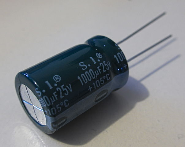
Capacitors are created out of two metal plates with an insulator between them. It’s one of the fundamental passive components used in electrical circuits and what makes them so special is their ability to store energy. They store potential energy in an electric field and give it back to the circuit when required. Each capacitor is built to have a specific amount of capacitance, which specifies how much electric charge it can store. Capacitance is measured in “Farads” and is abbreviated as “F”. The purpose of a capacitor is to resist sudden changes in voltage by supplying energy to a circuit.
Difference between Capacitor and Resistor
-
Basics of Capacitor and Resistor:
Capacitor and resistor are the two most common basic components used in electronic circuits with each can be described in terms of the relationship between the current flow and the voltage across the component. Both are energy storage components, but they differ in the way they store energy. A resistor is an electronic component used to resist the flow of current in a circuit. It’s more like a friction which restricts energy. A capacitor, on the other hand, is an electronic component used to store electrical charge. It generally opposes changes in current in electrical and electronic circuits.
-
Working of Capacitor and Resistor:
A resistor is a passive two-terminal electrical component that implements controlled amounts of resistance into electrical circuits meaning it restricts the amount of current flowing through a device. It doesn’t do anything actively to any electronic circuit; in fact, it’s simply hooked into a circuit to have the currents and voltages that you want precisely in your circuit. A capacitor, on the other hand, stores potential energy in an electric field and gives it back to the circuit when required. Simply put, it charges and discharges the electric charge stored in the circuit.
-
Function of Capacitor and Resistor:
A resistor is a little resistance package which controls the flow of current to other components in an electrical circuit. It’s not only used to amplify signals but to limit the flow of current, adjust signal levels, terminate transmission lines, etc. It limits the current flow to a safe value. A capacitor consists of two or more parallel conductor plates with an insulator between them. The function of a capacitor is to keep the positive and negative charges separated from each other. The effect of a capacitor is known as capacitance.
-
Measurement for Capacitor and Resistor
Resistance is the measure of the opposition to the flow of current in an electrical circuit and the unit of electrical resistance is “ohm” and is represented by Ω. It is defined by Ohm’s Law and is given as R = V/I, where V is the voltage drop measured in “volts” and I is the current flow of the resistor measured in “ampere”. Capacitance is the ability to store electrical energy which is defined as C = q/V, where q is the charges measures in “coulombs”, and V is the voltage measured in “volts”.
Capacitor vs. Resistor: Comparison Chart

Summary of Capacitor verses Resistor
Capacitor and resistor are the two basic components used in electrical and electronic circuits that are further classified into active and passive components. Active components control the flow of energy and are capable of introducing net energy into the circuit, whereas passive components cannot rely on a source of power and are incapable of controlling current by means of another electrical signal. Resistors and capacitors come under the category of passive components, except resistors limit the flow of current in a circuit, whereas capacitors provide reactance to the flow of current and are used to store electrical charge. They are the most essential components employed in various electrical or electronic circuits.
- Difference Between Caucus and Primary - June 18, 2024
- Difference Between PPO and POS - May 30, 2024
- Difference Between RFID and NFC - May 28, 2024
Search DifferenceBetween.net :
2 Comments
Leave a Response
References :
[0]Image credit: https://www.flickr.com/photos/oskay/437342078
[1]Image credit: https://upload.wikimedia.org/wikipedia/commons/thumb/8/83/S.I.-capacitor-20150807-003.jpg/604px-S.I.-capacitor-20150807-003.jpg
[2]Smith, Kenneth, et al. Electrical Circuits: An Introduction. Cambridge: Cambridge University Press, 1992. Print
[3]Bird, John. Electrical Circuit Theory and Technology (5th ed.). Abingdon: Routledge, 2014. Print
[4]Ergul, Ozgur. Introduction to Electrical Circuit Analysis. New Jersey: John Wiley & Sons, 2017. Print

I really like this website.
I wish one day I can be a very good electronic engineering
Am also in the GAMBIA at GTTI.
I thank all of you who managed to create this website, helping people to know more about electronics.
I really appreciate the site it’s very educative and easy to understand the explanation.Kudos to the creator of the site.JP Bello Ezekiel from Nigeria.